
تبلیغات
موضوعات
جستجو
صفحات جانبی
امکانات جانبی
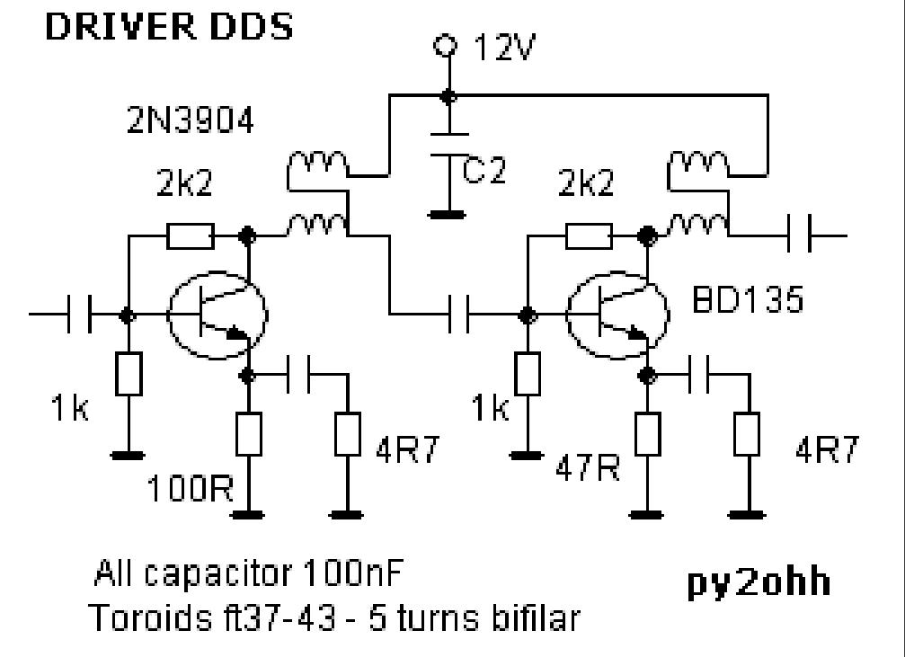
pllبرای فرستنده وگیرنده ها
pllبرای فرست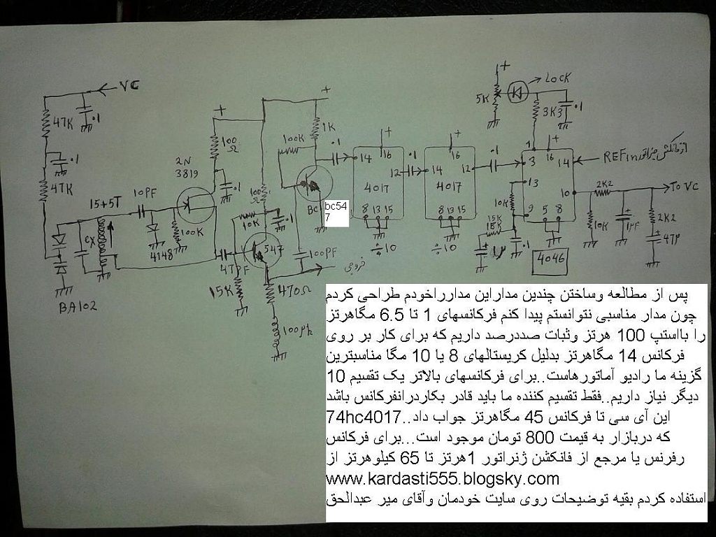 نده وگیرنده ها طرح از خودم
Simple, low cost AM SWBC Receiver
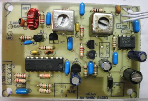
This project has been updated. This design was originally published 10 years ago (2004) and since then several parts have become discontiuned and no longer available. The part numbers for many of the parts have changed so they come up as "not found" when you go looking for them. Since FAR circuits recently made up some boards for this project, I decided it was time to update the information.
This AM Short Wave Broadcast Receiver is a reasonably simple, but effective design and can be built at low cost. It requires no adjustments to get to work and is more or less fool proof. This makes it a great beginners project, with little or no test equipment. The radio can be built for about $20.00, even if all new parts need to be bought. Many of the parts can be salvaged from an old AM/FM transistor or clock radio.
The radio will drive a small speaker to a comfortable volume. It will work with a short wire (3 feet or longer) or telescoping antenna. Tuning range is about 5.5 MHz to 10 MHz, using a coarse and fine tuning control. The radio can be powered by a 9 volt battery and draws about 21 ma of current. I would recomment using AA batteries or a small 9V AC adaptor to power the radio, as 9V radio batteries are expensive and won't last too long.

How it works:
The antenna is coupled into the mixer through C1, 100 pfd. The input to the mixer is tuned to about the receive frequency of interest by L1 and a poly-variable cap. The tuning cap can be a little hard to find as a new part, but can be salvaged from a dead or cheap AM/FM radio. (Poly-variables are available from qrpkits.com )
The mixer is an active stage using two JFETs in a cascode configuration. 2N3819's are shown, but just about any N channel JFET will work. The circuit was shamelessly borrowed from experimental Methods of RF Design" by W7OZI and co-anthers. This mixer exhibits about 13 dB of conversion gain. It requires a large amplitude Local Oscillator drive, which makes directly coupling to the square wave output of the 74HC4046 VCO quite acceptable.
The output of the mixer is tuned to the IF frequency of 455 kHz by the IF transformer T1. This is coupled into a cascode amplifier consisting of Q2 and Q3. This amplifier basically combines a common emitter amplifier to which the input signal is coupled to, with a common base amplifier which adds additional gain, but keeps the amplifier quite stable. The output of this stage is again tuned with a 455 kHz IF transformer. The combination of the two IF transformers gives the radio some selectivity.
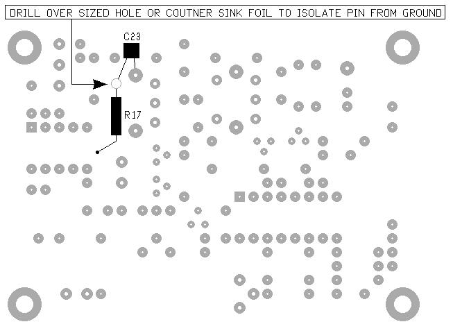
The AM signal is detected by a Shottky diode on the output of T2. A Shottky is used due to its low forward drop voltage, which reduces the level needed to detect a signal by at least 3 times over a silicon diode. The diode is connected to the volume control, which in turn goes to a LM386 audio amp. Forward bias was added to the detector diode to improve small signal sensitity and improves the audio quality. R17 supplies the bias and C23 by-passes the RF. These parts need to be added to the bottom of the circuit board.
The Local Oscillator uses the Voltage tuned R/C oscillator section of a 74HC4046 PLL. This part is capable of generating a signal up to about 30 MHz. C18 and R11 comprise the R/C part of the oscillator. The R/C oscillator isn't very stable and constantly bounces around a few 100 Hz. Fortunetly, the wide bandwidth of the IF and the nature of AM modulation is such that the instablility is not noticable to any great extent.
The original design was set up to just tune three SWBC bands and used a bank of three resistors selected by a switch to set the center of the tuning frequency to those bands. The TI chip tunes a wider frequency range so the voltages which need to be set for each band become farily close to each other, making it difficult to come up with standard values for the divider. Plus there is the problem of parts tollerances which will cause the exact voltages needed for a specific frequency to vary unit to unit.
The best way to solve this delema was simply to make continues tuning. Spaning large frequency range with a single turn pot makes for some very touchy tuning, so a fine tune control was added. Or you could use a 10 turn pot, but those are expensive. Trimmer resistors could have been used to set the center frequency for each band, but the board was not set up for that and now that boards have been made, too late to change.
WARNING: Not all 74HC4046s are created equal. The values shown are for the CD74HC4046N made by Texas Insturments (which is currently the only supplier of new through hole versions of this part). Parts made by a different manufacturer will require different values. Probably radically different values. The origninal CMOS 4046 parts will not work, as they have a much lower maximum operating frequency.
Construction:
Parts list and assembly drawings at bottom of page.
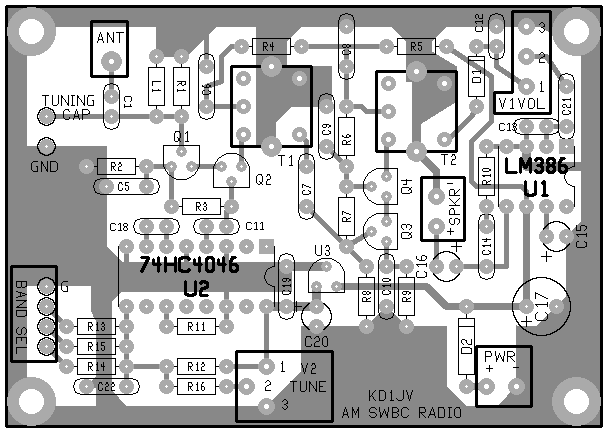
If you can make your own circuit boards, the layout and component location screen is avaiable as SWBC_PCB.pdf . A premade circuit board is also available from FAR Circuits for $5.00. (note, if you get the FAR board, there is a missing hole for one of the pins for T2 which you will have to drill).
Assembly is straight forward. It is easiest to start with the resistors, then the IC's, then the caps and so on. Note that the lead spacing for the resistors is very tight for 1/4 W resistors. You may want to use 1/8 W instead.
Adding some forward bias to the detector diode improves sensitivity and fidelity of the received signal. This is done be isolating the normally grounded pin of T2 secondary and adding a resistor between the pin and plus supply and adding a bypass cap between the pin and ground. Since the hole for this pin is missing from the board supplied by FAR curcuits, using a common 1/16" drill bit to make the hole should be big enough. Just be careful not to short to the foil around the hole when adding the components to the pin. You could also use an XACTO knife to cut the foil.
A frequency counter can be connected to pin 4 of U2, the 74HC4046. This is a 5 volt square wave. A 6 digit LED counter with programable IF offset can be bought direct from China for about $15US. This makes a nice digial dial, but draws an additional 90 ma. Set the dial for negative IF offset. In this mode, it will add the IF offset to the VFO frequency. Note that these counters clip the input to 600 mv with diode clamps which will load down the output of the '4046. In this case, add a series resistor of 3.3K or there abouts bewteen the coutner input and 4046 output.
The two IF transformers should come set close enough to the same frequency so they don't need adjustment. But if you must (and we must) try and peak the signals, adjust just one transformer and NEVER touch the other. Otherwise, you will chase the center frequency up and down the adjustment range of the coils!
The input tuning is sharp enough that it will require frequent re-peaking as the coarse frequency is tuned up and down the tuning range.
Parts list
| Designator | Value | Mouser part number | Price as of 11/04 | |
| C | poly-variable 20-180p | salvage from AM/FM radio | or www.qrpkits.con | |
| C5 - 10,14,19,21,22 | .1 uFd (10 TOTAL) | 80-C317C104M5U | $0.12 each | |
| C1, C11, C18 | 100 pFd NPO / C0G | $0.06 each | ||
| C12,C13 | .001 uFd | 140-50P2-102K | $0.08 each | |
| C15,C20 | 4.7 uFd /16V | 140-XRL16V4.7 | $0.06 each | |
| C16/C17 | 100 uFd / 16V | 140-XRL16V47 | $0.06 | |
| L1 | 4.7 uHy | 434-22-4R7 | $0.20 | or 34T on T37-2 |
| R8/12 | 15K 5% 1/4W | 291-15K | $0.07 10 min order | ($1.98 / 200!) |
| R2/4/5/9 | 100 ohm 5% 1/4W | 291-100 | ||
| R3/14/17 | 100K 5% 1/4W | 291-100K | ||
| R1/6/7/13/16 | 22K 5% 1/4W | 291-22K | ||
| R10 | 10 ohm 5% 1/4W | 291-10 | ||
| R11 | 3.3K 5% 1/4W | 291-3.3K | 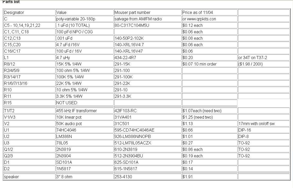 |
|
| R15 | NOT USED | |||
| T1/T2 | 455 kHz IF transformer | 42IF103-RC | $1.07each (need two) | |
| V1/V3 | 10K linear pot | 31VA401 | $1.25 (need two) | |
| V2 | 50K audio pot | 31C501 | $1.13 | 17mm with on/off sw |
| U1 | 74HC4046 | 595-CD74HC4046AE | $0.66 | DIP-16 |
| U2 | LM386N | 926-LM386N/NOPB | $1.01 | DIP-8 |
| U3 | 78L05 | 512-LM78L05ACZX | $0.27 | TO-92 |
| Q1/2 | 2N3819 | 610-2N3819 | $0.86 each | TO-92 |
| Q2/3 | 2N3904 | 512-2N3904BU | $0.19 each | TO-92 |
| D1 | SD101A | 625-SD101A | $0.17 | |
| D2 | 1N5817 | 615-1N5817 | $0.14 | |
| speaker | 3" 8 ohm | 253-4130 | $1.91 |
AD9850 DDS based Antenna Tuner Adjustment Aid
ARDUINO project
AD9850 DDS based Antenna Tuner Adjustment Aid

If you use a manual antenna tuner to match your transmitter to the antenna, not causing QRM while your making the adjustments can be an issue.. This project eliminates that problem by using a very low level signal and a very sensitive SWR bridge.
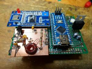
An inexpensive Arduino board is use to control a AD9850 DDS module and LCD display, while a handful of discrete parts comprise the SWR bridge. A simple LED is used as the match indicator.
Operation:
It is very simple.
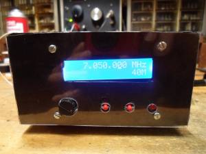
A preprogrammed frequency for each of the HF bands, 160 to 10 meters is selected by repetitively pushing the [ CHANGE BAND ] switch. I programmed in the various QRP calling frequencies in the CW segment of each band. You can of course change that in the Sketch by changing the frequency (freq) in the band look up table.
The operating frequency can be changed using a rotary encode with Gray code output. If the frequency changes in X2 steps, you have an encoder with quadature output.
The default tuning rate is 10 kHz, which allows for quickly moving the frequency to another part of the band. The tuning rate can be changed by pushing the [ CHANGE RATE] button. 10 Hz, 100 Hz, 1 kHz and 10 kHz rates can be selected. The active decade for tuning is indicated by the cursor underscore of the selected decade.
Note that tuning limits are enabled so you can't tune outside of the selected Ham band.
Once the desired band and frequency is selected, the [ TRANSMIT ] toggle switch is used to turn the DDS signal on and off. .
When the [ TRANSMIT ] switch is closed, the DDS is loaded with the frequency data, a 600 Hz sidetone is generated and Pin 8 is set HIGH, which can be used to control a power amplifier or switch over relay. When the [ TRANSMIT ] switch is open, it loads 0 Hz into the DDS chip, effectively turning it off. You don't want to leave it on or there will be a birdie at that frequency in your receiver.
You will of course need a coax switch ( or relay) to switch the antenna tuner between this device and your rig.
With the tuning aid connected to your tuner, adjust the tuner to make the indicator LED go out or to dim as much as possible.
Theory of operation:
The SWR bridge and indicator:
The SWR bridge is a Whetstone configuration, with the antenna in the unknown leg of the bridge. If the resistance of each leg is equal, there is no voltage difference between the center of the two legs, which indicates a match. I used 51 ohm resistors in the bridge as their close enough to 50 ohms, but if you do want an exact 50 ohm match, use 100 ohm resistors in parallel instead.
The bridge is driven by the square wave output of the AD9850, through a simple L/C low pass filter to remove most of the harmonics. With out this filter, harmonic from the square wave drive will reflect back and keep the LED from going completely out or at least get very dim. The filter starts to roll off at about 2 MHz so there is still enough harmonic energy when operating below 30 meters and the best you can do is make the LED very dim. You can still achive a 1:1 match without using the low pass filter, but the dip is much harder to see.
If the resistance of the unknown leg is not equal to the value of the other three resistors in the bridge, there is a voltage difference between the centers of each leg. This voltage is coupled to a high gain darlington amplifier using a step up transformer. R1 and R2 supply just enough voltage bias to the base of Q1 to improve the sensitivity without actually turning it on. A LED in series with Q2 which provides a visual indication of the amount of current flowing into the amplifier. The greater the imbalance of the bridge, the greater the voltage inputted to the amplifier and the greater the current in the collector path. The is only one potential problem with this method. If you live near a AM broadcast station you might pick up enough signal to keep the LED on all the time as you won't be able to balance the bridge at that frequency.
Construction:
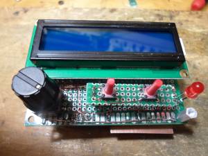
I intially used a UNO R3 board for develpoment, but used a NANO board for the final assembly. The schematic show wiring for the NANO board. Because the AD9850 and the LED back lighting of the display use a fair amount of current, a seperate 5V regulator is used to power these devices, rather then using the 5V regulator on the NANO board, as it would likely get very hot.
There are two types of AD9850 DDS modules available from China. I used the one with the two rows of 20 header pins and looks like a large DIP IC. If you use the other flavor, just follow the hook up diagram to connect to the required pins. These DDS modules are running about $10 at the time of this writing. Pretty amazing since the AD9850 chip costs $21 if you bought it all by it's self.
The LCD is a common 2 line, 16 character display. The ones with blue back lighting are very common and inexpensive. These run about $3.
All three of these major components can be obtained inexpensively direct for China buying with ebay. It just takes a few weeks to get them. If your in more of a rush, banggood.com can ship these from a US warehouse for a small price premium.
The rest of the discrete parts needed to build the SWR bridge and indicator can be obtained for the usual sources like Mouser or Jamesco. The MSP5179 transistors have a 1 GHz hft, so they still have decent gain at 28 MHz. You could sub the more common 2N3904's but it won't be as sensitive on the higher bands or may not work at all. If the LED does not light or is very dim at the higher frequencies, you don't have enough gain.
Since most of the componets are modules, I buit the project on a piece of FR4 pref board, using SIP sockets for the modules to plug into. The SIP sockets come in 40 pin strips. To cut them down to size, remove the pin one location past the number of pins you need and cut that slot with an hobby knife of razor saw. I use #28 heat stripable magnet wire to make all the interconnections. That way I don't need to strip insulated wire and makes for a neat looking wiring job.
The SWR bridge and amplifier could have been wired up right on the perf board, but I built it on a small scrap of copper clad board, dead bug style, which is a bit quicker and easier way to build it.
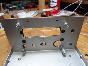
For final packaging, I recycled an old Radio Shack enclosure. Since the front panel of this box already had a number of holes in it (all in the wrong places, except for the display window, which was cut for a smaller display) I had to cover the old holes up somehow. I did this by simply putting down some double sided tape on the panel and then laid down a piece of black contruction paper and trimmed it to fit. This is then covered with a thin piece of clear Polycarbonate, which is easy to work with.
Programming the Arduino and the program "Sketch":
Hopefully your already familiar with the Arduino. If not a simple web search will come up with linksto the official Arduino web site with all the info you need.
The Sketch which you need is located in this zip file: Arduino_9850_sketch.zip
Once the Sketch has been downloaded into the Arduino board and everything is wired up, you will have to make one adjustment on the DDS module board. With the "unknown" leg of the bridge open, adjust the little trimmer resistor on the 9850 module until the SWR indicator LED comes on brightly. This trimmer sets the duty cycle of the square wave output and you want it more or less centered at 50%, but without a 'Scope just set it in about the middle of the adjustment range which makes the SWR LED stay on.
Parting thoughts:
This is my first Arduino "Sketch" and I'm pretty amazed I was able get it to work. I did take some late nights just to figure out how to do some simple things. I normally program directly in assembly which makes a whole lot more sense to me and is vasty more memory efficient and faster.
Although I designed this for the SWR bridge application, it can also be used as a signal generator, a transmitter VFO or even the VFO for a transceiver, although some modifications to the Sketch will be required for other applications.
For use as a signal generator with full tuning range, comment out the band limit tests in the DDSincerment() and DDSdecerment() routines and enable the max freq and min freq limits instead.
For a transceiver, you can add or subtract an offset to the base frequency before loading the DDS chip.
Anyway, I hope someone finds this project useful.
73, Steve KD1JV



wide band irf hf amplifier
با سلام
دوست عزيزم مهندس دل قوي توانستند با ترانزيستور هاي سويچ خانواده IRF تقويت باند پهن اچ اف بسازند
طرح اوليه متعلق به مهندس عاملي است كه با تغييراتي توسط مهندس دل قوي فعال شده و خروجي راديو گيرنده مولتي اس اس بي را 30-40 وات تقويت مي نمايد

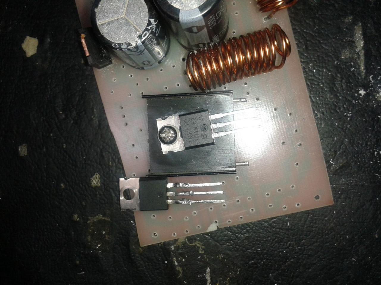
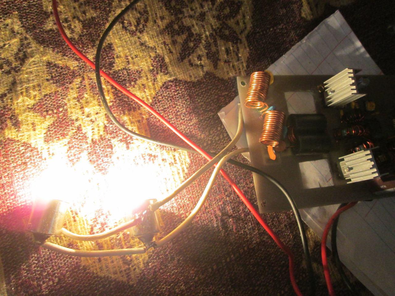
اصل طرح و نمونه برد مهندس عاملي
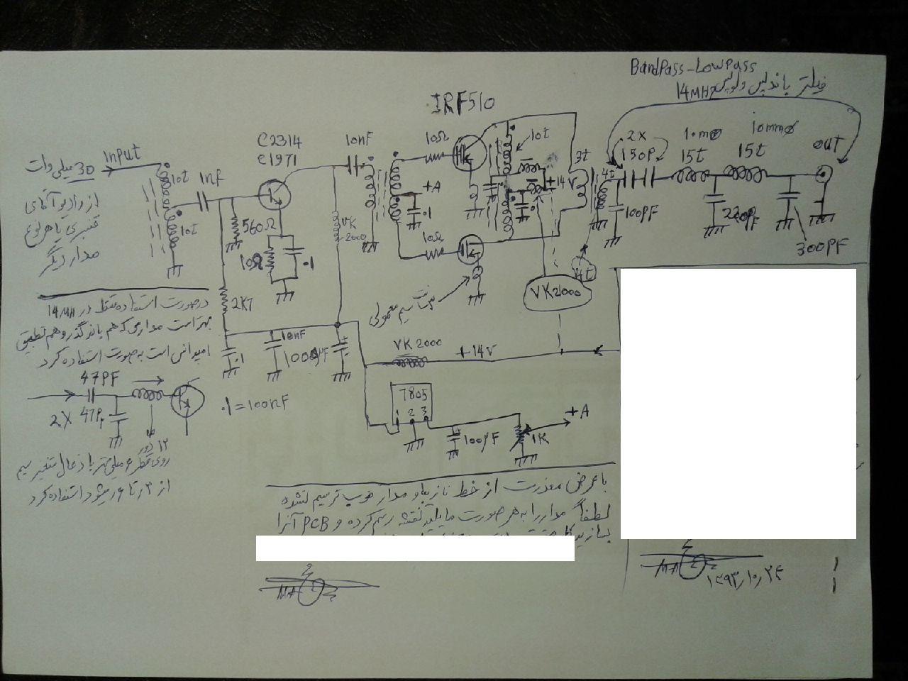
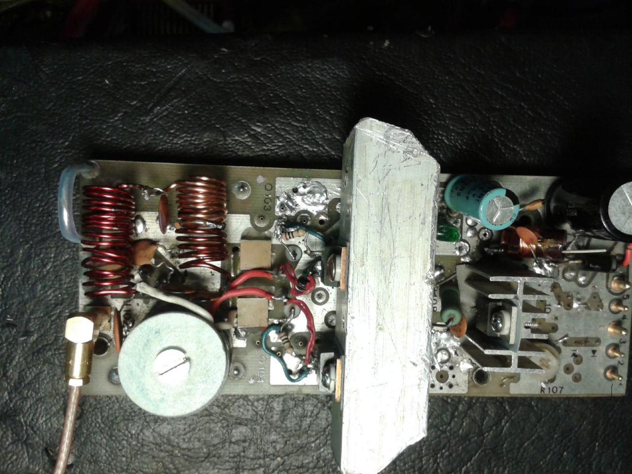
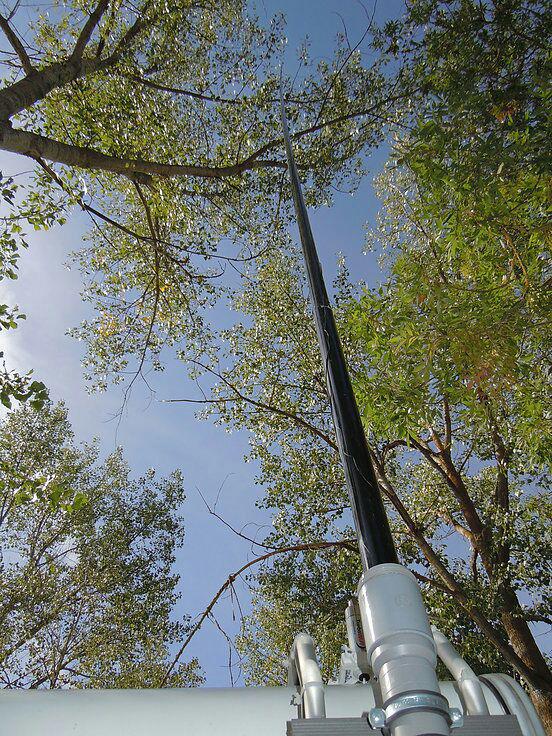
آنتن ميله اي تمام باند اچ اف
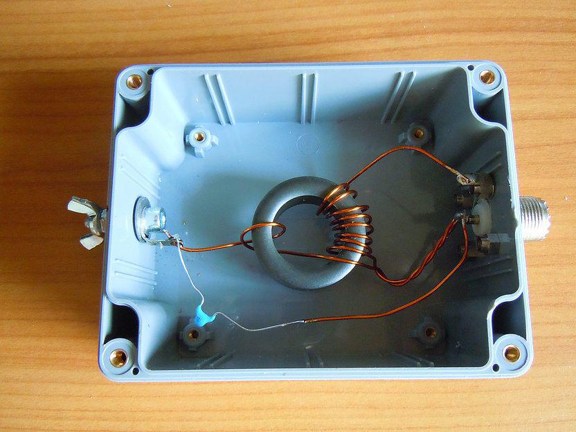
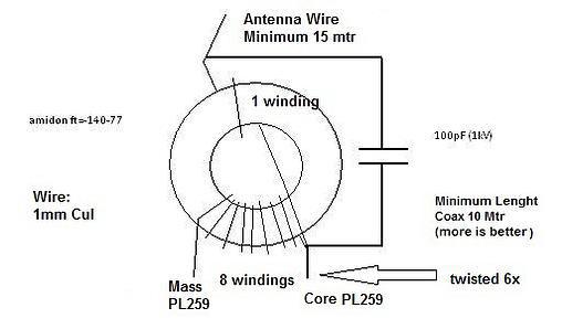
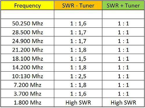
با سلام مدار جالبي براي تمام باند اچ اف با 15 متر سيم
طرح توسط مهندس حميد مثيمي اراعه شده است
ادرس اصل طرح و توضيحاتش:
http://gerritvinke.wix.com/hamradio-pa3dwc#!broadband-antenna/c158s
ورود کاربران
عضويت سريع
پشتيباني آنلاين
آمار
 آمار مطالب
 کل مطالب : 676 کل نظرات : 121
 آمار کاربران افراد آنلاین : 5 تعداد اعضا : 99
 آمار بازدید بازدید امروز : 131 بازدید دیروز : 152 ورودی امروز گوگل : 0 ورودی گوگل دیروز : 0 آي پي امروز : 2 آي پي ديروز : 1 بازدید هفته : 683 بازدید ماه : 3093 بازدید سال : 9883 بازدید کلی : 9883 اطلاعات شما آی پی : 216.73.217.113 مرورگر : سیستم عامل : امروز : دوشنبه 27 مهر 1405
آخرین نطرات کاربران
 جواد یاور مطلق - درود
 بلا بدور باشه مهندس !
انشالله همیشه سرحال سالم تندرست باشید !
.gif)
پاسخ:با درود و سپاس از لطف شما دوست گرامی بدرود - دوشنبه 08 دی 1404
گیرنده - از طرف کریم کاوه:سلام خسته نباشید لطف میکنید یک گیرنده hfبه من هدیه بدهید ممنون
شماره تماس:09353243076 - دوشنبه 08 دی 1404
یک هم وطن - من بدون مدار این رادیو ساختم باصدای واضح و بلند بدون برق و باطری پاسخ:باتشکر از لطفتان امیدوارم بقیه دوستان هم همت کنند و دست به اچار و هویه شده خودشان بسازند و لذت ساختن را ببرند چون در داشتن لذت نیست هنر ساختن است - دوشنبه 08 دی 1404
محسن علی بیگی - سلام خدا رو شکر که بخیر گذشت ، من هم اوایل سال psvt کردم میدونم خیلی سخته پاسخ:سلام ببخشید دیر پاسخ می دهم اینقدر گرفتار روز مرگی و هجویاتم که این مطالب فراموشم می شود بله اما با توکل و بستن زانوی اشتر مشکل حل می شود به امان خدا و توکل به او - دوشنبه 08 دی 1404
پرویز مهرزاد - سلام درود جناب عبداحق عزیز بسیار خوشحالم که وب سایت شما با مطالب مفید وعالی فعال شده است.پاسخ:باسلام و تشکر از لطف و مرحمت شما دوست عزیز و گرامی - دوشنبه 08 دی 1404
پرویز مهرزاد - سلام ودرود استاد عبدالحق عزیز بسیار خوشحالم که سایت جنابعالی بامطالب جدید وعالی دوباره فعلیتش را شروع نموده است.پاسخ:با سلام تذکر بجا و بموقعی بود بسیار متشکرم - دوشنبه 08 دی 1404
ایزدی - یه مشکلی داره این طرح. کل سلف ها با هم 12. 7 میکرو میشه که با خازن 270 پیکو، فرکانس مرکزی فیلتر 2.7 مگا هرتز می شه. کمترین سلف هم (0.1 میکرو) با همون خازن 270 پیکو 30 مگاهرتز رو رد می کنه. بنا بر این نیازی به خازن های دیگه نیست. دوستان دیگه نظرشون چیه.پاسخ:باسلام و تشکر کل خازن ها و سلفها برای فرکانس 1800کیلو که ابتدای باند رادیو اماتوری است کم است و بسختی تنظیم می شود اما برای 3500 بله زیاد است - دوشنبه 08 دی 1404
سعید - با سلام استاد تو مدار برزیلی یه رله داریم این کارش چیه ؟ مثلا اگر رله فعال بشه چی میشه؟ یه کلید جا گذاری شده براش .
تو قسمت ورودی موج vfo به 7358 یه cwkeyزده به پایه 3 همین آیسی برای چیه؟
ce keyسرچ کردم کلید مورس آمد میشه توضیح بفرمایید ممنون میشم .
پاسخ:با سلام هنگام فشردن کلید PTT روی میکروفون پایه دوم سیم پیچ رله موجود در مدار زمین شده و سر دیگر این رله به مثبت باطری وصل است باعث عملکرد رله شده و لذا دوکنتاکت ان عمل کرده یکی ورودی گیرنده را بزمین وصل می کند تا امواج فرستنده وارد گیرنده نشده و اسیب نرسانند کنتاکت دیگر رله هم ولتاژ مثبت تغذیه را که در حالت معمولی به خط مثبت گیرنده وصل است قطع و خط مثبت فرستنده را فعال می کند +tx cw key بله کلید مورس است که برای کاردر حالت مورس مولد موج جدا داشته که بجای میکروفون کار کرده و سیگنال را ارسال می کند - دوشنبه 08 دی 1404
هومن - سلام بنده یکی از علاقمندان لامپ هستم . و 10 سال اخیر را بر روی مدارات لامپی کار کردم .با سرچ اینجا را پیدا کردم .می خواستم ببینم در زمینه مخابرات فعالیت لامپی در ایران هست ؟
این مطلب راجب لامپ واقعا توجه مخاطب علاقمند را جلب می کند ؟
من فکر می کنم نویسنده اصلا راجب لامپ حس خوبی ندارد .عذر خواهی می کنم
پاسخ:سلام دوست عزیز از صراحت و فصاحت بیان شما خوشحالم مطلبتان راجع به نویسنده مطلب لامپ کمی کم لطفی و شاید سخت گیری در بر دارد نویسنده مطلب استاد عاملی بزرگ رادیو اماتوری ایران هستند و مطلب را بی اندازه ساده و اسان گفتند چون اکثر جوانها از لامپ و ولتاژ کار ان وحشت داشته و تقریبا هیچ نمی دانند اما ظاهرا شما در مورد لامپ مطلع و ازموده هستید لذا برخود نگیرید شما هم اگر در مورد لامپ و یا مطالب استاد عاملی نقد و نظری دارید بسیار خوشحال می شوم مکتوب بفرمایید تا در همان بخش یا در بخش جدید بنام خودتان منتشر شود
پاسخ:https://t.me/joinchat/AAAAAEJj30AwLGIyi_UQ3g - دوشنبه 08 دی 1404
سعیدی - سلام استاد بنده بی جواب ماندم .gif)
پاسخ:با سلام و پوزش از تاخیر طبق تجربه دوستان این مدار به دلیل نامرغوب بودن قطعات نو موجود در بازار معمولا در ابتدا کار نمی کند لذا بتوصیه استاد عاملی بهنر است از قطعات اوراقی رادیو و ضبط ها استفاده شود قطعات معمولا در گیر این رادیو ابتدا ای سی سویچ یا کلید زنی است که یک مدل خاصش برای مدار مناسب است و مدلهای دیگر فرکانس کار و ولتاژشان مناسب نیست درمورد ای سی مدولاتور و دمدولاتور 3028 این ای سی هم بشدت مورد شک و شبهه است در موردی باتعویض 5 عدد ای سی دو عدد که بهتر بود در مدار بکار گرفته شد لذا بهترین روش استفاده از مرحله مرحله و گام بگام کار کردن رادیو است ضمن انکه اگر فرستنده کار بیفتد گیرنده هم کار خواهد کرد و بالعکس لذا شما می توانید مدار را از میکروفون در حالت فرستنده یا بلندگو در حالت گیرنده شروع نمایید و اگر مسیر سیگنال جدا باشد در نقشه شما می توانید از تقویت صدا شروع کرده و به دمدولاتور رفته و سپس به فیلتر و بعد میکسر وی اف او و در اخر به فیلتر تنظیم باند بروید و حد اکثر سیگنال و حساسیت را بدست اورید پس فیلتر های رادیویی یا بقول شما توکو ها قسمت اخر تنظیم و تعقیب مدارتان است اگر شد برای اطلاع شما و سایر دوستان مدار را در حالت گیرنده و فرستنده جدا اراعه خواهم داد یا با رنگ مسیر سیگنال را جدا می کنم که راحت تر باشد اگر شما عضو تلگرام هستید در یکی از گروه های رادیو اماتوری بیایید و مستقیما با دوستان سازنده و استفاده کننده رادیو تماس گرفته راهنمایی شوید اگر نه ادرس ایمیلتان را بدهید تا راهنمای مونتاژ را برایتان بفرستم
پاسخ:http://py2ohh.w2c.com.br/trx/ararinhamontagem/montandoararinha.htm
راحل مونتاژ و تست مدار است - دوشنبه 08 دی 1404
آرشیو
- آبان 1404
- شهریور 1404
- مهر 1402
- آذر 1400
- آبان 1400
- اردیبهشت 1399
- اسفند 1397
- آبان 1397
- مهر 1397
- خرداد 1397
- فروردین 1397
- اسفند 1396
- بهمن 1396
- دی 1396
- آذر 1396
- آبان 1396
- شهریور 1396
- مرداد 1396
- تیر 1396
- خرداد 1396
- فروردین 1396
- اسفند 1395
- بهمن 1395
- دی 1395
- آذر 1395
- آبان 1395
- مهر 1395
- شهریور 1395
- مرداد 1395
- تیر 1395
- اردیبهشت 1395
- فروردین 1395
- اسفند 1394
- بهمن 1394
- دی 1394
- آذر 1394
- آبان 1394
- مهر 1394
- شهریور 1394
- مرداد 1394
- تیر 1394
- خرداد 1394
- اردیبهشت 1394
- فروردین 1394
- اسفند 1393
- بهمن 1393
- دی 1393
- آذر 1393
- آبان 1393
- مهر 1393
- شهریور 1393
- مرداد 1393
- تیر 1393
- خرداد 1393
- اردیبهشت 1393
- فروردین 1393
- اسفند 1392
- بهمن 1392
- دی 1392
- آذر 1392
- آبان 1392
درباره ما
-
به وب سایت من خوش امدید
در این مقوله علاقمندم اطلاعاتی از رادیو اماتوری که در ذهن داشته و در حال پاک شدن هستند را یادآوری و بهمراه عکس و مطلب جهت اطلاع علاقمندان درج و در این زمینه هر گونه همکاری و اعلام نظر و بیان ایرادات مزید بر منت خواهد بود.
ورود کاربران
خوش آمدید! لطفا وارد حساب خود شوید