
تبلیغات
موضوعات
جستجو
صفحات جانبی
امکانات جانبی
شهادت امام رضا علیه السلام
به توکل نام اعظمت
*آمده ام ، آمدم ای شاه پناهم بده*
*خط امانی ، ز گناهم بده*
*ای حرمت ، ملجأ درماندگان*
*دور مران از درو راهم بده*
*لایق وصل تو که من نیستم*
*اذن به یک لحظه نگاهم بده*
***السلام علیک یا علی ابن موسی الرضا (ع)*** .
ادرس لینک جناب مهندس عاملی
با سلام و تسلیت ایام
جهت اطلاع و ارتباط دوستان علاقمند به مسایل رادیو اماتوری ایران و اطلاع از طرح ها و نقشه های مهندس عاملی ادرس تلگرامی ایشون رو اراعه می کنم تا جمع علاقمندان بهتر بتوانند از نظرات و ایده ها و توضیحات فنی ایشون بهتر استفاده بفرمایند
https://telegram.me/ep2ma
امیدوارم علاقمندان رادیو اماتوری ایران بتوانند با ارتباط با ایشون و مطالب فنی ایشون بهتر و بیشتر از امکانات و توانائی های داخل مملکت استفاده کرده و از وجود ایشون بهره مند بشوند
طرح های مهندس دل قوی
با سلام و تسلیت ایام اربعین سالار شهیدان
چندین عکس از کارهای مهندس دل قوی جهت اطلاع دوستان و تشویق ایشان:

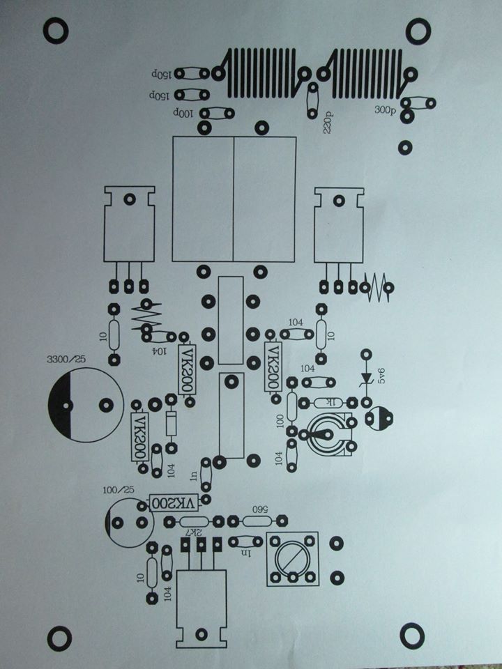
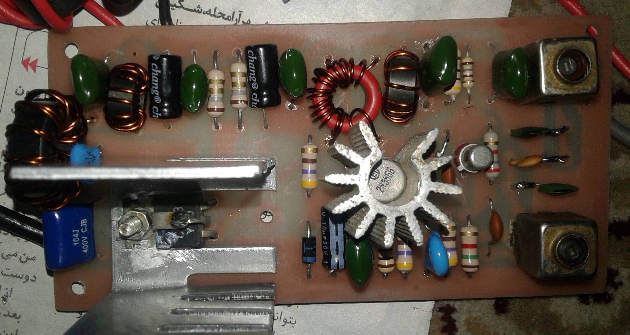
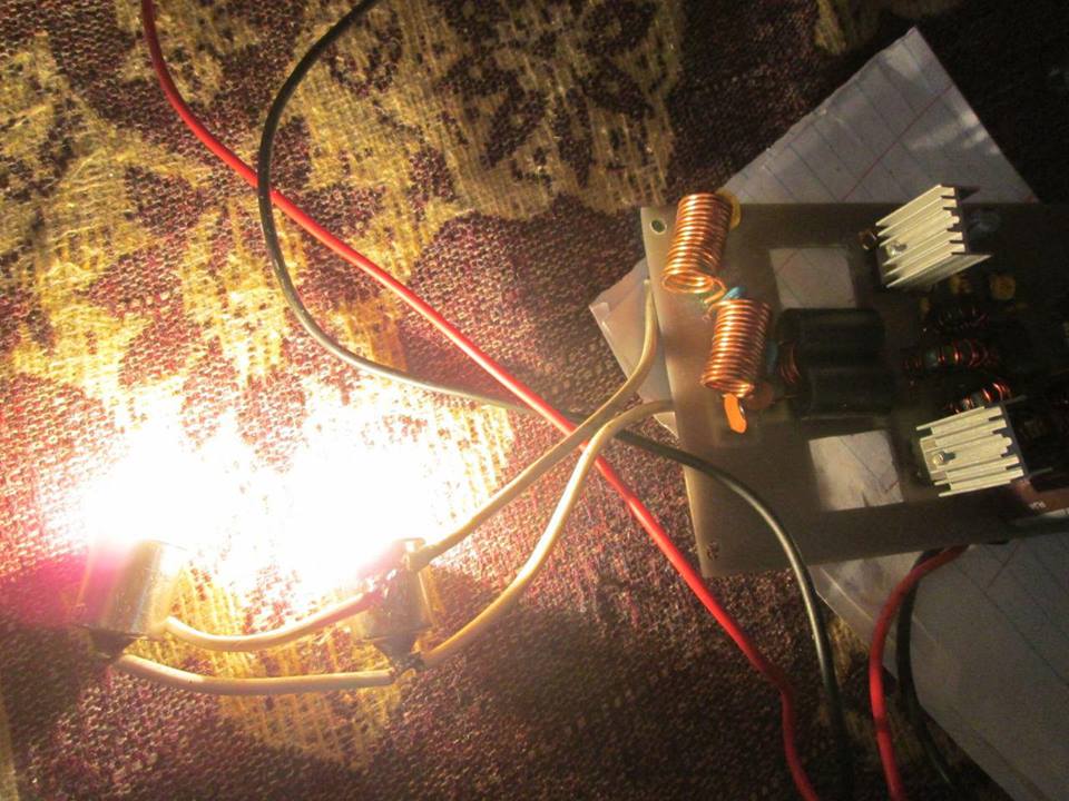
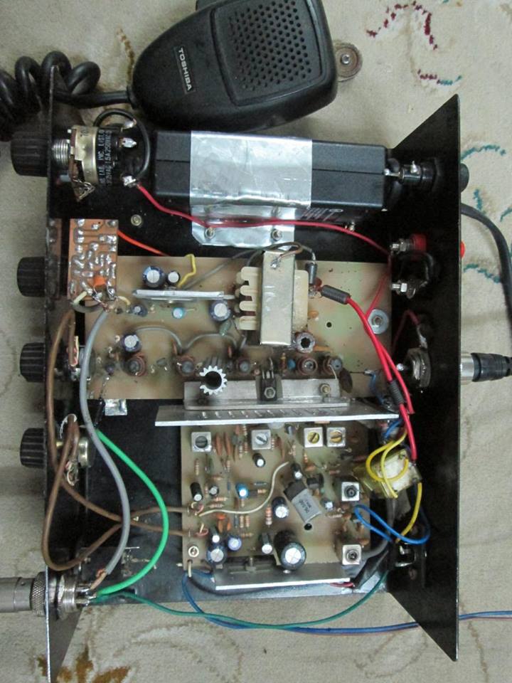
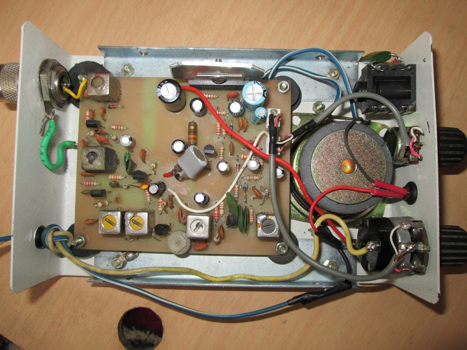
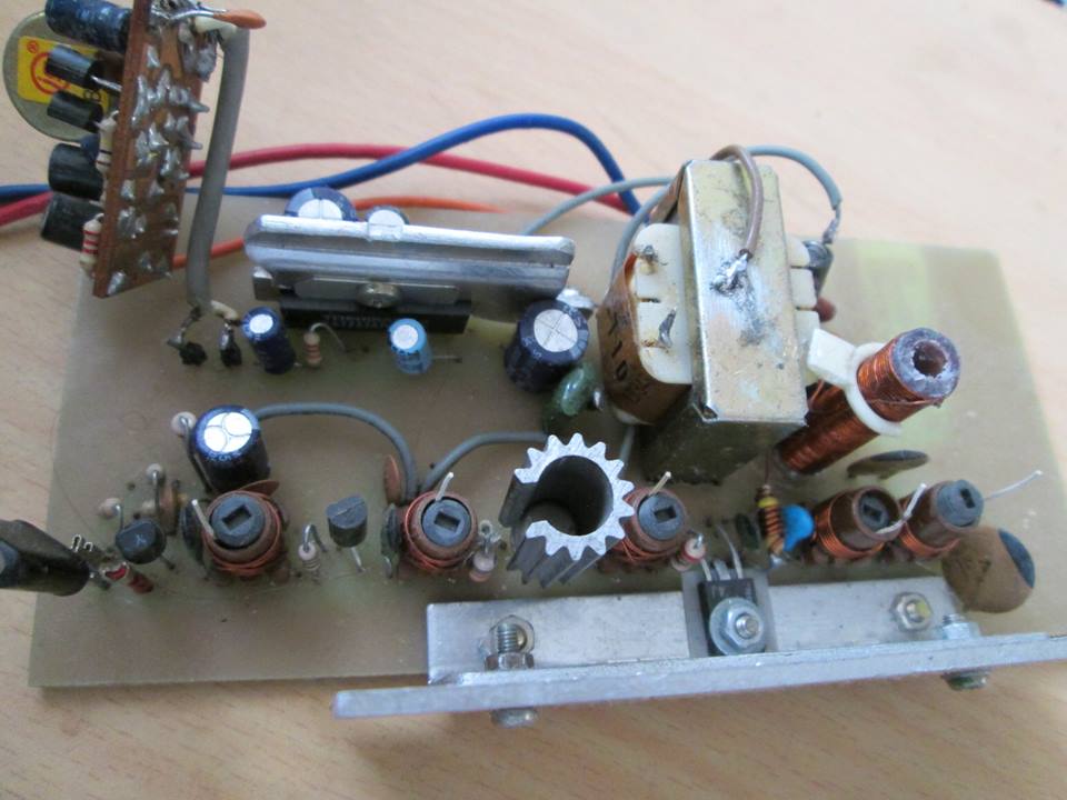
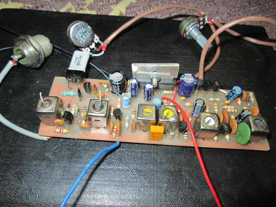
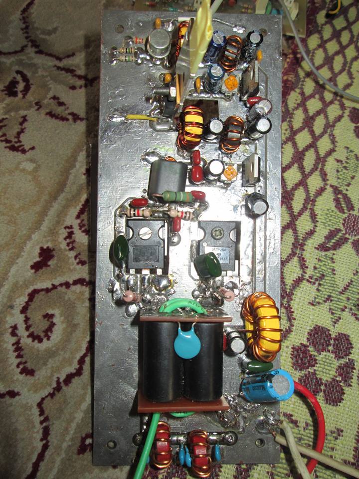
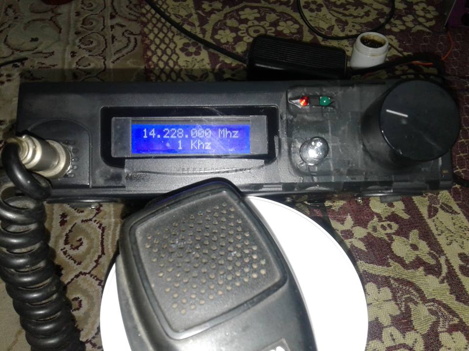

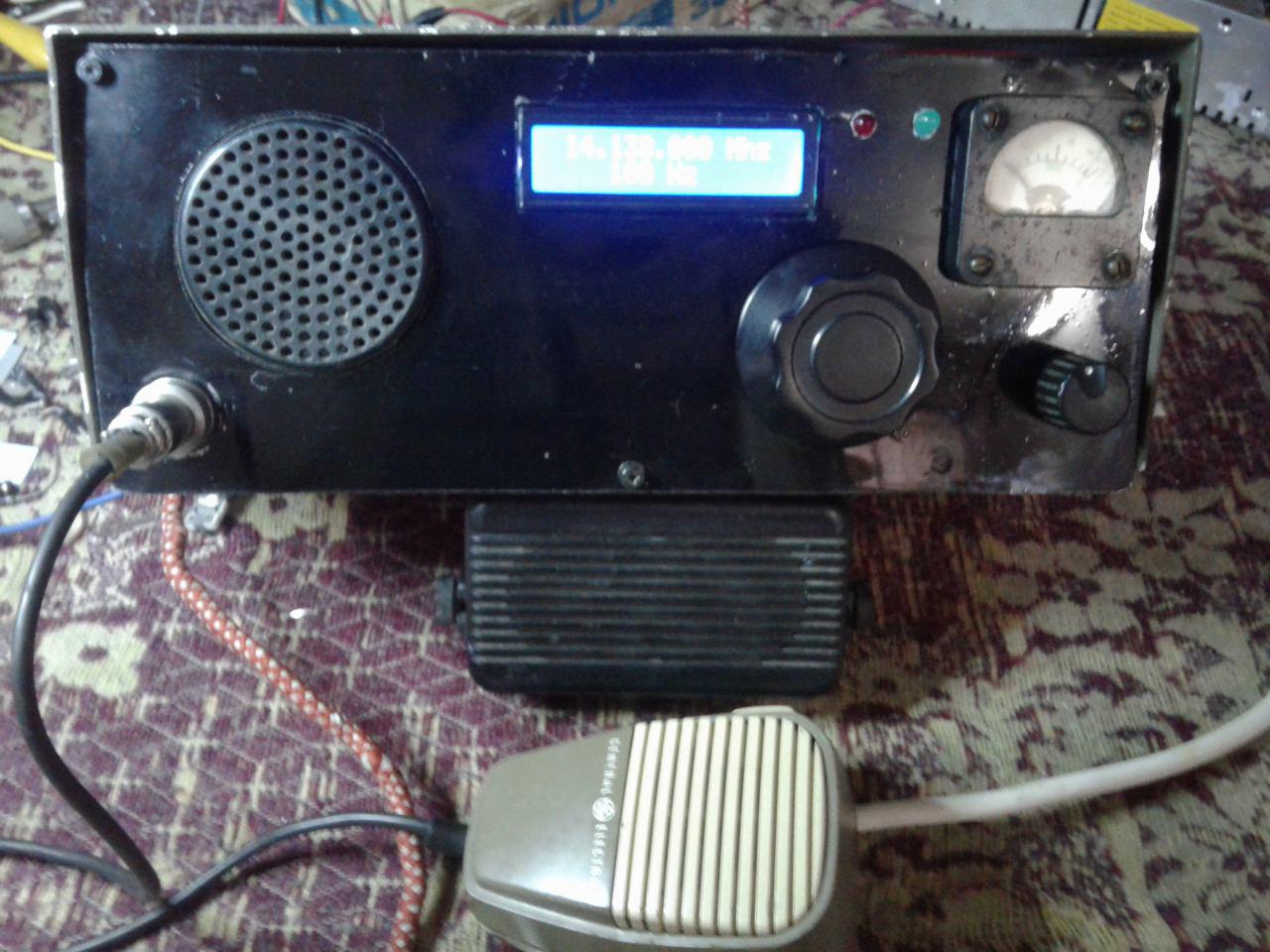

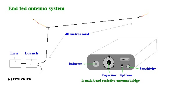
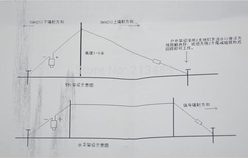
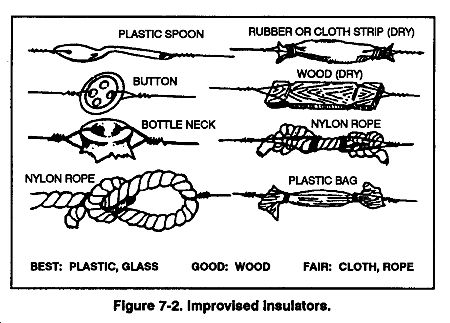
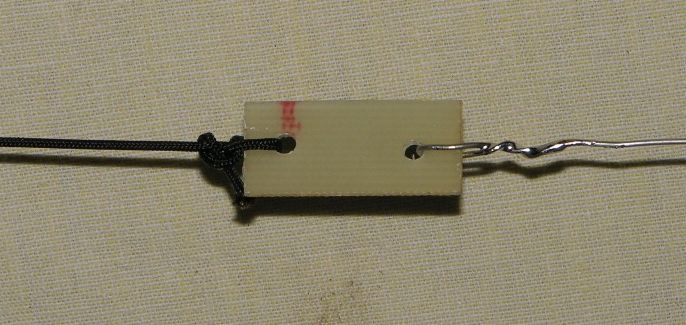
آنتن برای 14 مگا
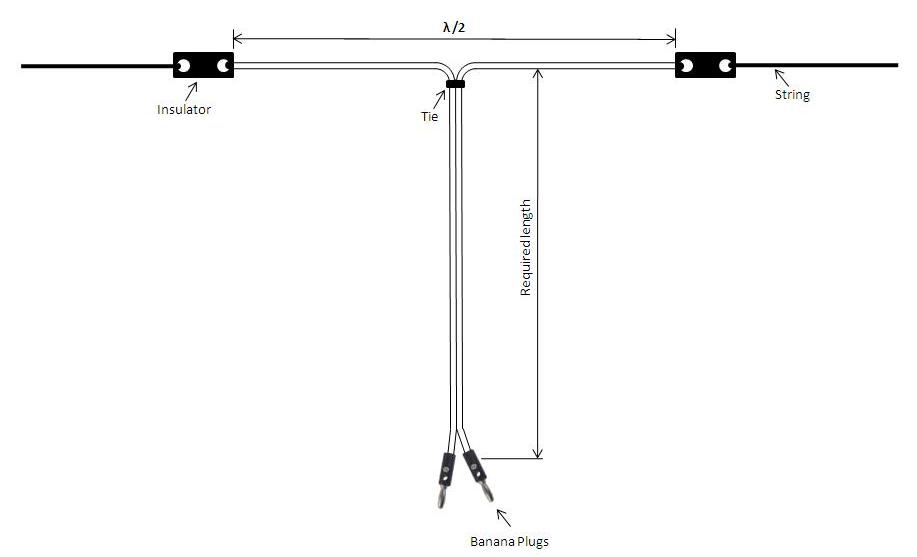
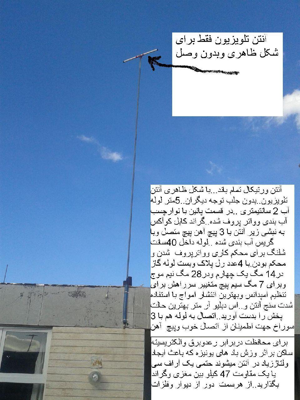
با سلام و آرزوی سلامتی و موفقیت روز افزون دوستان
انتن برای باند 20 متر یا 14 مگا بروش ساده تشکیل شده از :
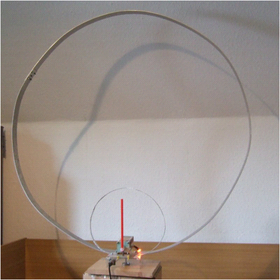
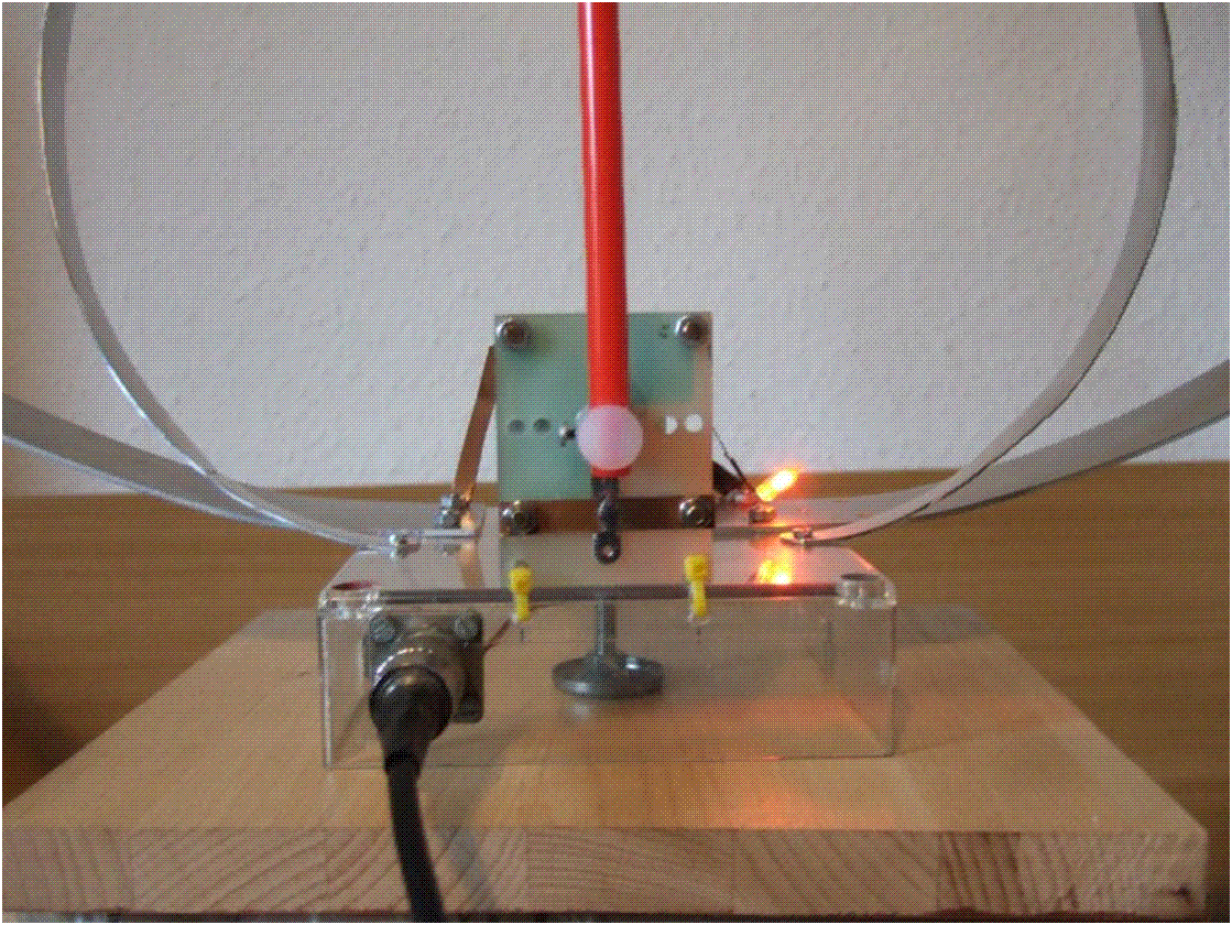
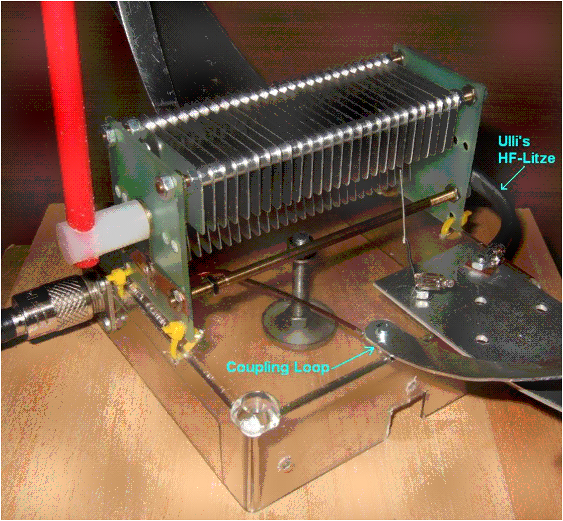
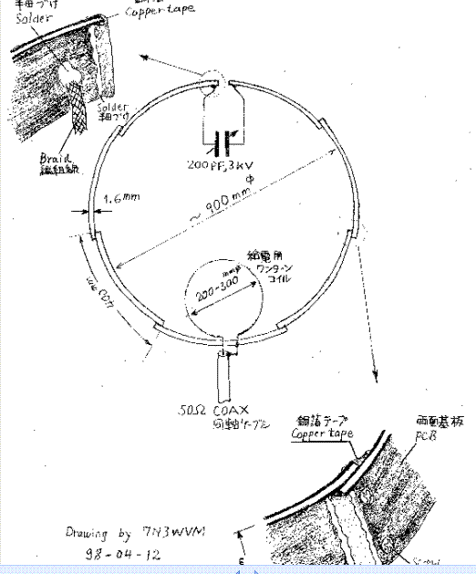
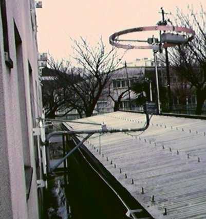
multi band radio
با سلام
اخیرا دوستان طرح تقویت کننده ای را معرفی کردند که بسیار جالب و کارامد بود و دوستم مهندس دل قوی اصل انرا پیدا کرده و در اختیار دوستان عزیز قرار دادند
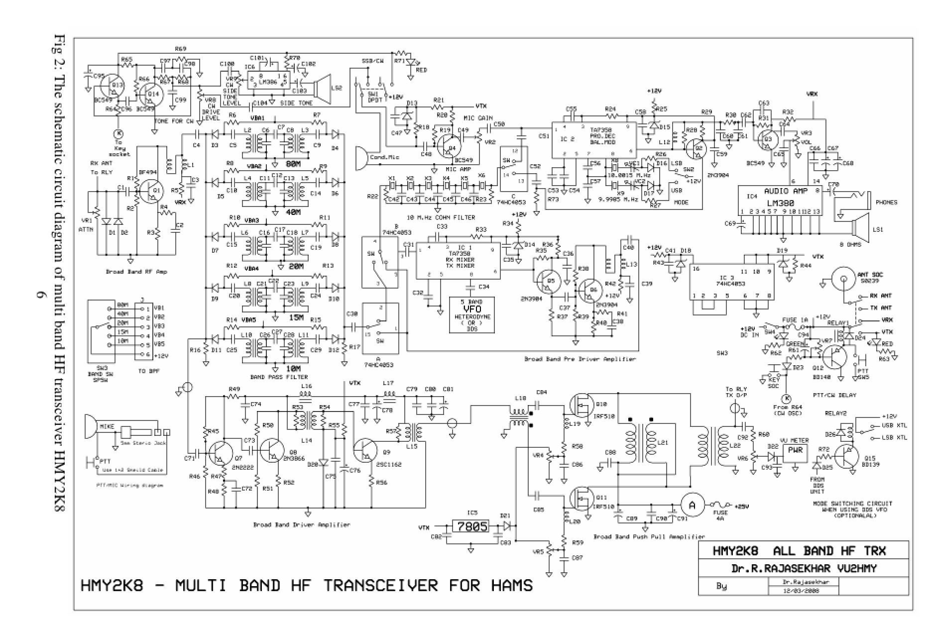
http://www.4qdtec.com/mostest.html
A better test
What the test above actually measures is the pinch-off voltage: the highest voltage that can be put on the MOSFET's gate without it starting to conduct. The circuit below shows a better way.
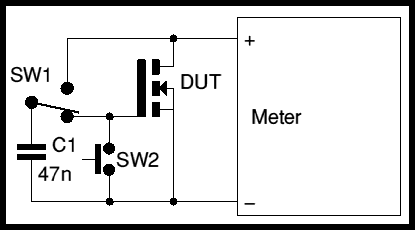
There are two push switches, one is a changeover switch, the second is a push to make (normally open). I use a couple of microswitches. It uses the diode test of a multimeter, or you could use any power supply, or a 9v battery, with a resistor in series with the MOSFET to limit the current.
With both switches in the normal position, the capacitor C1 charges up to the open circuit voltage of the diode tester. The capacitor's value is not critical, 10n-100n is fine. When Sw1 is pushed, the charged capacitor is disconnected from the meter leads and reconnected to the MOSFET gate. The MOSFET should turn fully on, so the diode tester will indicate a short circuit.
Release Sw1. The MOSFETs gate is still charged. Only leakage will discharge it, so the MOSFET should still stay conducting for quite some time.
Push SW2 to short the MOSFETs gate to source, to discharge it. The meter should show an open-circuit.
Alternatively, connect the capacitor to meter +ve via a diode, to allow the capacitor to charge, Now when the capacitor is connected to the gate, the MOSFET will conduct but the diode will stop the conducting MOSFET from discharging the capacitor.
Meter Check of a Transistor (JFET)
http://www.allaboutcircuits.com/textbook/semiconductors/chpt-5/meter-check-transistor-jfet/
Testing a JFET with a multimeter might seem to be a relatively easy task, seeing as how it has only one PN junction to test: either measured between gate and source, or between gate and drain.
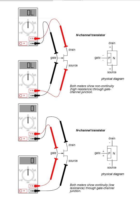
Testing continuity through the drain-source channel is another matter, though. Remember from the last section how a stored charge across the capacitance of the gate-channel PN junction could hold the JFET in a pinched-off state without any external voltage being applied across it? This can occur even when you’re holding the JFET in your hand to test it! Consequently, any meter reading of continuity through that channel will be unpredictable, since you don’t necessarily know if a charge is being stored by the gate-channel junction. Of course, if you know beforehand which terminals on the device are the gate, source, and drain, you may connect a jumper wire between gate and source to eliminate any stored charge and then proceed to test source-drain continuity with no problem. However, if you don’t know which terminals are which, the unpredictability of the source-drain connection may confuse your determination of terminal identity.
A good strategy to follow when testing a JFET is to insert the pins of the transistor into anti-static foam (the material used to ship and store static-sensitive electronic components) just prior to testing. The conductivity of the foam will make a resistive connection between all terminals of the transistor when it is inserted. This connection will ensure that all residual voltage built up across the gate-channel PN junction will be neutralized, thus “opening up” the channel for an accurate meter test of source-to-drain continuity.
Since the JFET channel is a single, uninterrupted piece of semiconductor material, there is usually no difference between the source and drain terminals. A resistance check from source to drain should yield the same value as a check from drain to source. This resistance should be relatively low (a few hundred ohms at most) when the gate-source PN junction voltage is zero. By applying a reverse-bias voltage between gate and source, pinch-off of the channel should be apparent by an increased resistance reading on the meter.
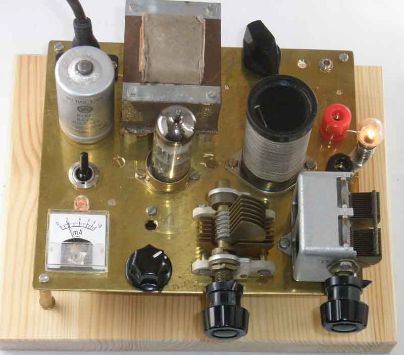
فرستنده لامپی
با سلام و تسلیت ایام شهادت سرور آزادگان جهان حسین ابن علی علیه السلام
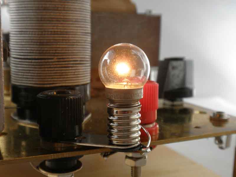
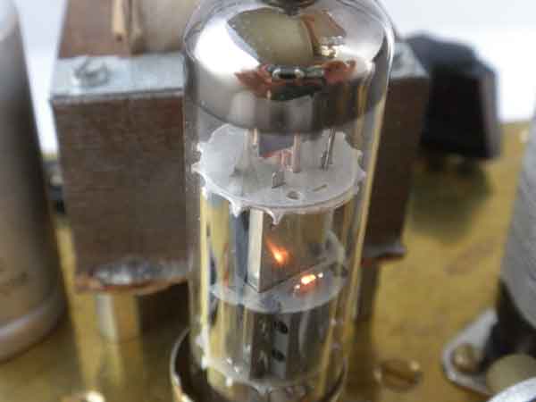
مدار فرستنده لامپی ساده ای بدستم رسید جهت اطلاع عزیزان تقدیم می گردد
http://www.sm7ucz.se/AM_Transmitter/AM_transmitter.htm
ECL85 medium wave AM-Transmitter
Men det kunde lika gärna ha varit ECL80, ECL82, ECL84 eller ECL86

ورود کاربران
عضويت سريع
پشتيباني آنلاين
آمار
 آمار مطالب
 کل مطالب : 676 کل نظرات : 121
 آمار کاربران افراد آنلاین : 2 تعداد اعضا : 99
 آمار بازدید بازدید امروز : 99 بازدید دیروز : 152 ورودی امروز گوگل : 0 ورودی گوگل دیروز : 0 آي پي امروز : 1 آي پي ديروز : 1 بازدید هفته : 651 بازدید ماه : 3061 بازدید سال : 9851 بازدید کلی : 9851 اطلاعات شما آی پی : 216.73.217.113 مرورگر : سیستم عامل : امروز : دوشنبه 27 مهر 1405
آخرین نطرات کاربران
 جواد یاور مطلق - درود
 بلا بدور باشه مهندس !
انشالله همیشه سرحال سالم تندرست باشید !
.gif)
پاسخ:با درود و سپاس از لطف شما دوست گرامی بدرود - دوشنبه 08 دی 1404
گیرنده - از طرف کریم کاوه:سلام خسته نباشید لطف میکنید یک گیرنده hfبه من هدیه بدهید ممنون
شماره تماس:09353243076 - دوشنبه 08 دی 1404
یک هم وطن - من بدون مدار این رادیو ساختم باصدای واضح و بلند بدون برق و باطری پاسخ:باتشکر از لطفتان امیدوارم بقیه دوستان هم همت کنند و دست به اچار و هویه شده خودشان بسازند و لذت ساختن را ببرند چون در داشتن لذت نیست هنر ساختن است - دوشنبه 08 دی 1404
محسن علی بیگی - سلام خدا رو شکر که بخیر گذشت ، من هم اوایل سال psvt کردم میدونم خیلی سخته پاسخ:سلام ببخشید دیر پاسخ می دهم اینقدر گرفتار روز مرگی و هجویاتم که این مطالب فراموشم می شود بله اما با توکل و بستن زانوی اشتر مشکل حل می شود به امان خدا و توکل به او - دوشنبه 08 دی 1404
پرویز مهرزاد - سلام درود جناب عبداحق عزیز بسیار خوشحالم که وب سایت شما با مطالب مفید وعالی فعال شده است.پاسخ:باسلام و تشکر از لطف و مرحمت شما دوست عزیز و گرامی - دوشنبه 08 دی 1404
پرویز مهرزاد - سلام ودرود استاد عبدالحق عزیز بسیار خوشحالم که سایت جنابعالی بامطالب جدید وعالی دوباره فعلیتش را شروع نموده است.پاسخ:با سلام تذکر بجا و بموقعی بود بسیار متشکرم - دوشنبه 08 دی 1404
ایزدی - یه مشکلی داره این طرح. کل سلف ها با هم 12. 7 میکرو میشه که با خازن 270 پیکو، فرکانس مرکزی فیلتر 2.7 مگا هرتز می شه. کمترین سلف هم (0.1 میکرو) با همون خازن 270 پیکو 30 مگاهرتز رو رد می کنه. بنا بر این نیازی به خازن های دیگه نیست. دوستان دیگه نظرشون چیه.پاسخ:باسلام و تشکر کل خازن ها و سلفها برای فرکانس 1800کیلو که ابتدای باند رادیو اماتوری است کم است و بسختی تنظیم می شود اما برای 3500 بله زیاد است - دوشنبه 08 دی 1404
سعید - با سلام استاد تو مدار برزیلی یه رله داریم این کارش چیه ؟ مثلا اگر رله فعال بشه چی میشه؟ یه کلید جا گذاری شده براش .
تو قسمت ورودی موج vfo به 7358 یه cwkeyزده به پایه 3 همین آیسی برای چیه؟
ce keyسرچ کردم کلید مورس آمد میشه توضیح بفرمایید ممنون میشم .
پاسخ:با سلام هنگام فشردن کلید PTT روی میکروفون پایه دوم سیم پیچ رله موجود در مدار زمین شده و سر دیگر این رله به مثبت باطری وصل است باعث عملکرد رله شده و لذا دوکنتاکت ان عمل کرده یکی ورودی گیرنده را بزمین وصل می کند تا امواج فرستنده وارد گیرنده نشده و اسیب نرسانند کنتاکت دیگر رله هم ولتاژ مثبت تغذیه را که در حالت معمولی به خط مثبت گیرنده وصل است قطع و خط مثبت فرستنده را فعال می کند +tx cw key بله کلید مورس است که برای کاردر حالت مورس مولد موج جدا داشته که بجای میکروفون کار کرده و سیگنال را ارسال می کند - دوشنبه 08 دی 1404
هومن - سلام بنده یکی از علاقمندان لامپ هستم . و 10 سال اخیر را بر روی مدارات لامپی کار کردم .با سرچ اینجا را پیدا کردم .می خواستم ببینم در زمینه مخابرات فعالیت لامپی در ایران هست ؟
این مطلب راجب لامپ واقعا توجه مخاطب علاقمند را جلب می کند ؟
من فکر می کنم نویسنده اصلا راجب لامپ حس خوبی ندارد .عذر خواهی می کنم
پاسخ:سلام دوست عزیز از صراحت و فصاحت بیان شما خوشحالم مطلبتان راجع به نویسنده مطلب لامپ کمی کم لطفی و شاید سخت گیری در بر دارد نویسنده مطلب استاد عاملی بزرگ رادیو اماتوری ایران هستند و مطلب را بی اندازه ساده و اسان گفتند چون اکثر جوانها از لامپ و ولتاژ کار ان وحشت داشته و تقریبا هیچ نمی دانند اما ظاهرا شما در مورد لامپ مطلع و ازموده هستید لذا برخود نگیرید شما هم اگر در مورد لامپ و یا مطالب استاد عاملی نقد و نظری دارید بسیار خوشحال می شوم مکتوب بفرمایید تا در همان بخش یا در بخش جدید بنام خودتان منتشر شود
پاسخ:https://t.me/joinchat/AAAAAEJj30AwLGIyi_UQ3g - دوشنبه 08 دی 1404
سعیدی - سلام استاد بنده بی جواب ماندم .gif)
پاسخ:با سلام و پوزش از تاخیر طبق تجربه دوستان این مدار به دلیل نامرغوب بودن قطعات نو موجود در بازار معمولا در ابتدا کار نمی کند لذا بتوصیه استاد عاملی بهنر است از قطعات اوراقی رادیو و ضبط ها استفاده شود قطعات معمولا در گیر این رادیو ابتدا ای سی سویچ یا کلید زنی است که یک مدل خاصش برای مدار مناسب است و مدلهای دیگر فرکانس کار و ولتاژشان مناسب نیست درمورد ای سی مدولاتور و دمدولاتور 3028 این ای سی هم بشدت مورد شک و شبهه است در موردی باتعویض 5 عدد ای سی دو عدد که بهتر بود در مدار بکار گرفته شد لذا بهترین روش استفاده از مرحله مرحله و گام بگام کار کردن رادیو است ضمن انکه اگر فرستنده کار بیفتد گیرنده هم کار خواهد کرد و بالعکس لذا شما می توانید مدار را از میکروفون در حالت فرستنده یا بلندگو در حالت گیرنده شروع نمایید و اگر مسیر سیگنال جدا باشد در نقشه شما می توانید از تقویت صدا شروع کرده و به دمدولاتور رفته و سپس به فیلتر و بعد میکسر وی اف او و در اخر به فیلتر تنظیم باند بروید و حد اکثر سیگنال و حساسیت را بدست اورید پس فیلتر های رادیویی یا بقول شما توکو ها قسمت اخر تنظیم و تعقیب مدارتان است اگر شد برای اطلاع شما و سایر دوستان مدار را در حالت گیرنده و فرستنده جدا اراعه خواهم داد یا با رنگ مسیر سیگنال را جدا می کنم که راحت تر باشد اگر شما عضو تلگرام هستید در یکی از گروه های رادیو اماتوری بیایید و مستقیما با دوستان سازنده و استفاده کننده رادیو تماس گرفته راهنمایی شوید اگر نه ادرس ایمیلتان را بدهید تا راهنمای مونتاژ را برایتان بفرستم
پاسخ:http://py2ohh.w2c.com.br/trx/ararinhamontagem/montandoararinha.htm
راحل مونتاژ و تست مدار است - دوشنبه 08 دی 1404
آرشیو
- آبان 1404
- شهریور 1404
- مهر 1402
- آذر 1400
- آبان 1400
- اردیبهشت 1399
- اسفند 1397
- آبان 1397
- مهر 1397
- خرداد 1397
- فروردین 1397
- اسفند 1396
- بهمن 1396
- دی 1396
- آذر 1396
- آبان 1396
- شهریور 1396
- مرداد 1396
- تیر 1396
- خرداد 1396
- فروردین 1396
- اسفند 1395
- بهمن 1395
- دی 1395
- آذر 1395
- آبان 1395
- مهر 1395
- شهریور 1395
- مرداد 1395
- تیر 1395
- اردیبهشت 1395
- فروردین 1395
- اسفند 1394
- بهمن 1394
- دی 1394
- آذر 1394
- آبان 1394
- مهر 1394
- شهریور 1394
- مرداد 1394
- تیر 1394
- خرداد 1394
- اردیبهشت 1394
- فروردین 1394
- اسفند 1393
- بهمن 1393
- دی 1393
- آذر 1393
- آبان 1393
- مهر 1393
- شهریور 1393
- مرداد 1393
- تیر 1393
- خرداد 1393
- اردیبهشت 1393
- فروردین 1393
- اسفند 1392
- بهمن 1392
- دی 1392
- آذر 1392
- آبان 1392
درباره ما
-
به وب سایت من خوش امدید
در این مقوله علاقمندم اطلاعاتی از رادیو اماتوری که در ذهن داشته و در حال پاک شدن هستند را یادآوری و بهمراه عکس و مطلب جهت اطلاع علاقمندان درج و در این زمینه هر گونه همکاری و اعلام نظر و بیان ایرادات مزید بر منت خواهد بود.
ورود کاربران
خوش آمدید! لطفا وارد حساب خود شوید